

Home
Overview
Benefits
Customer
Gallery
G3i
Installation
Instructions
Magneto
Modifications
MSD
Reference
Spec.
Supercharging
Air/Fuel
Delivery
Dyno Runs
Order
Price Sheet
Contact Us
G3i -
INSTALLING THE G3i INTERFACE
The G3i interface module can be installed with good useable working magnetos. If the magnetos are in need of a rebuild or need disassembly inspection repair, then this must be done first before installing the G3i system. Magneto modifications, ignition parts and service are all available though G3i if needed.
Step1. Locate a good place to mount the G3i and the MSD 6a ignition modules on the Aircraft. Mounting the modules together or on an aluminum plate makes the wiring easy. The color-coded leads that come out of the G3i connect exactly to the same color coded leads on the MSD 6a ignition module.
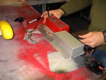
Laying out the module locations on the mounting
plate. Mounting the modules on a plate is not
required, however this is a clean easy way to
mount them together.
Checking clearances before final mounting.
Step 2. In the G3i interface system, the existing magneto coils become the common element for the secondary high voltage discharge to the spark plugs. The way this is done is the positive lead from the magneto coil is disconnected and re-routed out of the magneto to the G3i.
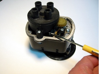
Step 3. This is done to both the left and right magnetos and can be done on or off the engine. If you decide to remove the magnetos to do the positive primary coil lead re-routing, then check where the timing is set at and make a note of it. Also take a good look at the amount of room around the magneto so that when the coil drive stud/ BNC is installed it does not interfere with any existing engine accessories.
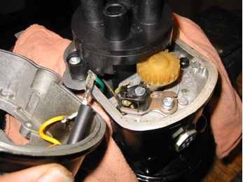
Step 4. With the magnetos on the bench there are no modifications to the timing of the distributor rotor or contact set. The top contact cover must come off to gain access to the primary coil lead and remove the female spade connector for the primary coil lead from the contact points. This will be connected to the coil drive stud/ BNC. Depending on whether they are Bendix or Slick magnetos, the location where the coil wire stud will be in different locations.
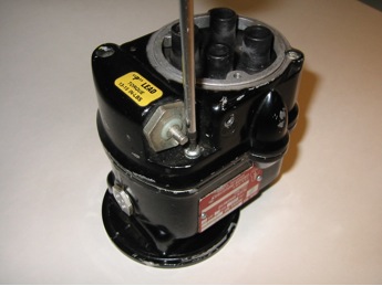
After the Slick magnetos are removed, the top
cover must be removed to gain access to the
contact set (also known as points) and coil lead.
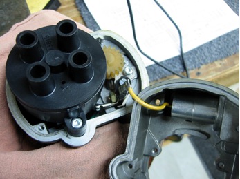
When the top cover is removed there is only 1 wire
(yellow) coming from the capacitor to the contact set.
This will be removed from the contact set for now.
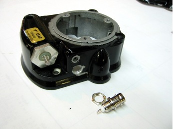
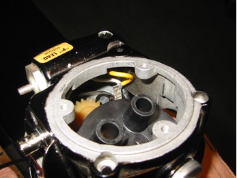
The top cover has been located and drilled
for this application to fit a BNC terminal.
This will be the in-put source for the magneto coil.
Here’s the BNC terminal installed with the
male spade terminal. Note how the wire is routed.
Next, the coil lead female spade terminal
is removed from the contact set.
The white BNC terminal wire is the connected
to the coil lead female terminal. 2 layers of
heat shrink tubing will insulate the connection.
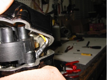
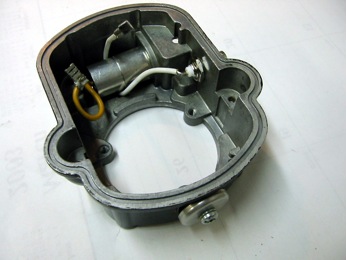
Re-connect the capacitor lead (yellow) back to
its original terminal and route the new coil
lead from the BNC terminal around it.
Here you can see the capacitor lead connected
and the routing of the new coil driver lead.
A final look before closing.
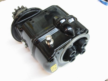
Right Slick magneto ready for install.
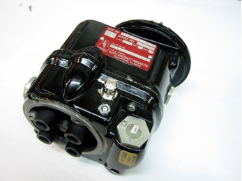
Left Slick magneto ready for install
The magnetos will be installed as normal. A standard magneto-timing tool will be used to synchronize them at the factory suggested timing spec. In this installation, the left magneto will provide the pip signal to trigger the MSD ignition through the G3i module. This will fire both magnetos in perfect synchronization. When the G3i module is on.
Step 5. There will also be the need to route switched 12-volt power from a toggle and a 12-volt power supply for the MSD 6a ignition needs. The G3i module draws .7 amps while the MSD 6a will draw an average of 2.4 to 3.7 amps. Total systems under higher 3000+ RPMS draw in the range of 4 to 6 amps. Connect to a 12-volt power source as shown for your application.
This is the most typical installation layout for the G3i and MSD ignition modules. There are more layout schematics depending on the different requirements you may have. The schematic shown is the one Brandon used for his RV6 with an O-360, with Slick 4300 series magnetos. Left magneto has a retard impulse coupler.
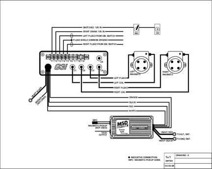
Click here for larger view of schematic in a new window (pdf).
Step 6. Re-install the magnetos back on the engine and re-set the ignition timing of the magnetos as in the normal sequence. The original p-leads that came from the existing ignition switching are re-routed to the G3i module input terminals. The new p-leads from the G3i out-put BNC connectors replace the original left and right magneto p-lead connections. Hook up the coil driver leads from the G3i out-put BNC connectors to the magneto coil driver studs/ BNC.
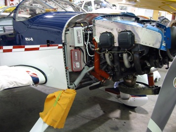
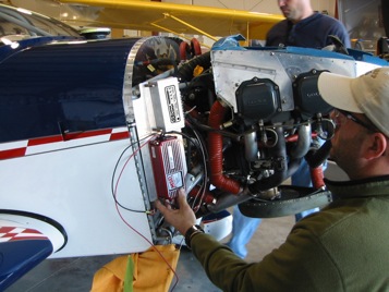
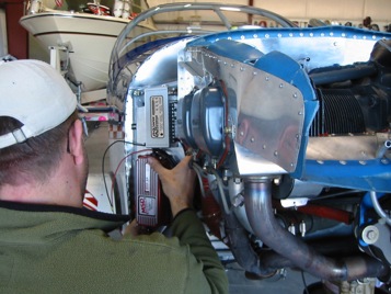
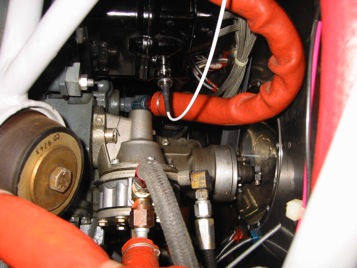
The G3i and the MSD ignition modules mounted
on an aluminum plate in the engine compartment
right side near the firewall with WDG clamps to
engine mount. The original P-leads were long
enough to reach this location.
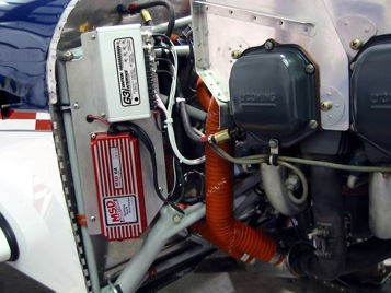
The modules are shown up close.
The G3i supplied power is switch from a
toggle on the instrument panel near the
left & right mag switches. The main power
for the MSD is supplied from the switch
side of the master solenoid.
Left magneto shown with coil driver lead hooked up.
Home Overview Benefits G3i Install Mag Mod MSD Reference
Customer Gallery Spec. Dyno Order/Pricing Contact Us
All work Copyright ©2016 G3I All Rights Reserved